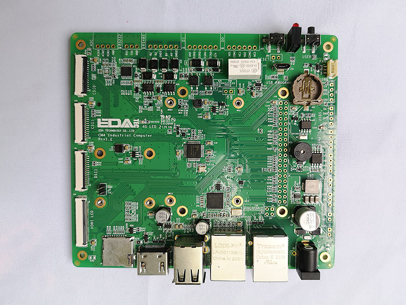
From ordinary electronics to aerospace electronics, the application of PCBA printed circuit board has developed for many years. The progress of materials and the upgrading of process capability are also changing. The demand for circuit boards in more and more industries has been widely reflected. Especially this year, with the shortage of chips, many brands of cars have been unable to deliver. Especially this year's engine ECU control module; System interaction module; There is a special shortage of GPS positioning module chips, which also poses a certain challenge to our manufacturers specializing in automotive electronic SMT chip processing. If it is an external factor, the market will adjust over a period of time, but the factory should really consider the improvement of automotive electronics PCBA assembly process. It needs to select appropriate materials and specific design to meet the requirements of applicable vehicle specification level standards. Therefore, it is suggested to follow the following basic strategies in SMT processing of automobile circuit board.
1. SMT component mounting direction
The direction of component mounting plays an important role in the performance, reliability and function of PCBA circuit board manufacturing. When wave soldering is used, the element must be oriented parallel to the wave crest to prevent bridging welding or open circuit.
2. Through hole treatment
There are many control modules that need signal transmission in automotive electronics. It is necessary to protect sensitive signals (such as communication modules) from electrical radiation interference through plane and controlled impedance. Each layer must use 2 to 4 through holes for connection between high current layers; In fact, using multiple vias on a PCB can improve reliability, reduce resistance and inductance losses, and increase thermal conductivity.
3. Thermal management
Components with rated power exceeding 10MW or 10mA must require appropriate thermal management and power management components. The power and ground layers must be placed on the inner layer. If symmetrical and central elements prevent bending of the plate. The first step includes identifying the most significant heat generating components and calculating what heat management measures to take. Therefore, the routing thickness, number of layers, thermal path continuity and circuit board surface must be strictly controlled, which are all factors affecting the climate of working components.
The thermal via has the same effect as the copper field. Both tend to increase conductivity. Using multiple soil areas and power supplies directly connected to the heat source through thermal vias can significantly reduce the operating temperature. If multiple components generate large amounts of heat, it is best to distribute them evenly on the board to avoid hot spots. On the other hand, if the heat generator is concentrated in multiple components, it is best to place it in the middle of the plate so that the heat is evenly dispersed in all directions.
These are some factors that can effectively improve product quality summarized in the case of automotive electronic processing.


